
Busy Tag AT Command Manual FW 2.0
This document describes the complete USB/serial AT command set exposed by Busy Tag firmware 2.0.
1. Introduction
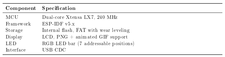
Busy Tag is a smart status display. It is driven entirely over a USB CDC serial link using an AT command protocol. The device exposes a front RGB LED bar, an LCD display capable of showing PNG and animated GIF images, and internal ash storage with a FAT file system.
1.1 Key Features
- RGB LED bar - solid colors, custom multi-step patterns, and 25 built-in animations.
- LCD display - shows stored PNG and GIF images and solid color fills.
- USB CDC interface - complete AT command set for control and file transfer.
- Internal storage - FAT file system with wear leveling for images and data files.
- Temperature & diagnostics - internal die temperature, reset reasons, chip and bootloader info.
1.2 Hardware Specifications
2. Getting Started
2.1 USB Connection
Connect Busy Tag to a host with a USB cable. The device enumerates as a USB CDC serial port. Open it with any serial terminal.

2.2 Testing the Connection
> AT
OK
2.3 Command Format
- Read / query: AT+<CMD>? or AT+<CMD>?
- Write / set: AT+<CMD>=<parameters>
- Action: AT+<CMD>
Every command line must terminate with \r\n (CR+LF). Commands are case-insensitive.
2.4 Response Format
- Data + success: a +<PREFIX>:<data> line followed by OK.
- Simple success: OK
- Error: ERROR :<code> - see Section 8.
- Prompt: > - the device is waiting for a data payload (file or pattern body).
- Event: +evn:<type>,<data> - asynchronous notification (e.g. image shown).
3. Device Information
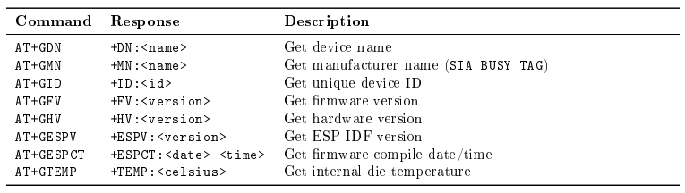
> AT+GDN
+DN : busytag -5 F83C0
OK

> AT+GID
+ID :240001ABC123
OK

> AT+GFV
+FV :2.0
OK
> AT+GHV
+HV :1.0
OK

> AT+GESPV
+ESPV : v5 .1.2 - dirty
OK

> AT+GTEMP
+TEMP :42.5
OK
4. LED Control
The front RGB LED bar has 7 addressable positions, selected with a 7-bit bitmask (0-127). 127 (binary 1111111) selects all LEDs. Colors are given as RRGGBB hex.
4.1 Solid Color

> AT+SC=127 , FF0000               # all LEDs red
OK

> AT+SC=127 ,0000FF                # all LEDs blue
OK

# The pins value is a 7 - bit mask , one bit per LED ( LED1 =1 , LED2 =2 , LED3 =4 , LED4 =8 , ...).
> AT+SC=7 ,00FF00                  # first three LEDs (1+2+4) green
OK

> AT+SC=8 , FFFFFF                 # fourth LED only ( bit 4) white
OK

> AT+SC? + SC :127 ,0000FF
OK
4.2 Custom Patterns
A custom pattern is a sequence of steps, each: <pins>, <RRGGBB>,<speed>,<delay> where speed and delay are in milliseconds.
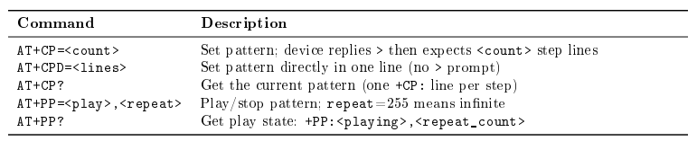
# Define a 2 - step pattern ( red , then green ) , each 100 ms with 500 ms hold
> AT+CP=2
>
+CP :127 , FF0000 ,100 ,500
+CP :127 ,00FF00 ,100 ,500

OK

> AT+CP?
+CP :127 , FF0000 ,100 ,500
+CP :127 ,00FF00 ,100 ,500
OK

# Same 2 - step pattern set in a single line.
# Steps use the + CP : prefix and are separated by a literal \r\n.
> AT+CPD=+CP :127 , FF0000 ,100 ,500\ r \ n + CP :127 ,00FF00 ,100 ,500
OK

> AT+PP=1,3                  # play 3 times
OK
> AT+PP=1,255                # play forever
OK
> AT+PP=0,0                  # stop OK
5. Display Control
5.1 Display Brightness
> AT+DB?
+DB :75
OK
> AT+DB =50                  # set display brightness to 50%
OK
5.2 Showing Images
Busy Tag displays PNG and GIF files stored in its file system.

> AT+GPL
+PL:logo.png ,2048
+PL:animation.gif ,8192
OK

> AT+SP=animation.gif
OK
+evn:SP,animation.gif

> AT+SP?
+ SP:animation.gif
OK
6. File Management
6.1 Storage Information
> AT+GFSS                     # free storage , bytes
+FSS :1048576
OK
> AT+GTSS                     # total storage , bytes (3 MB partition )
+ TSS :3145728
OK
6.2 File Operations
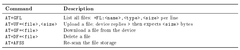
> AT+GFL
+FL:config.json , json ,256
+FL: def.png , png ,1024
OK

# Upload a 12-byte file
> AT+UF=test.txt ,12
>
Hello World!
OK

# Read a file back
> AT+GF=config.json
+ GF:config.json ,256
{ ... file content ... }

> AT+DF=old_file.txt
OK

7. System & Reset Commands

7.1 Reset Reason Codes
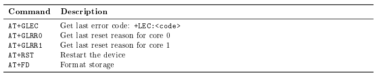
AT+GLRR0 and AT+GLRR1 return the last reset reason for CPU core 0 and core 1 as a numeric code (+LRR0:<code> / +LRR1:<code>).
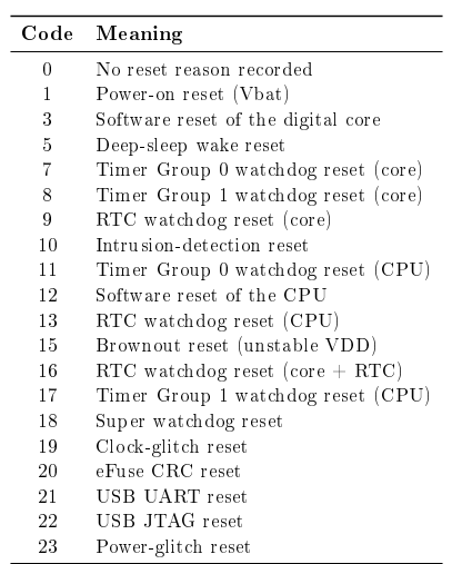
> AT+GLRR0
+LRR0:1                    # core 0 last reset : power - on
OK

> AT+GLRR1
+ LRR1:12                  # core 1 last reset : software reset of the CPU
OK
8. Error Codes
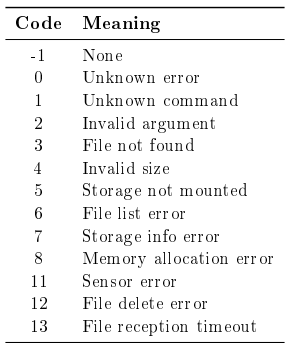
On failure the device responds with ERROR:<code>. The last error is also retrievable with AT+GLEC.
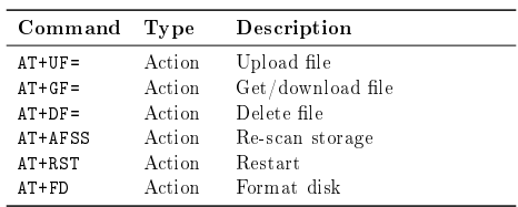
9. Complete Command Reference
10. Programming Example
All examples open the USB CDC serial port at 460800 baud, send each command terminated with \r\n, and read the +.../OK reply line

10.1 Python
import serial

ser = serial.Serial('COM3 ', 460800 , timeout=1)

def  cmd(c):
     ser.write((c + "\r\n").encode())
     return ser.readline().decode().strip()

print(cmd("AT"))                       # OK
print(cmd("AT+GFV"))                   # +FV :2.0
cmd("AT+SC=127,0000FF")                # all LEDs blue
cmd("AT+DB=60")                        # display brightness 60%
cmd("AT+SP=logo.png")                  # show an image

ser.close()
10.2 C#
using System;
using System.IO.Ports;

var port = new SerialPort ("COM3",460800) { NewLine = "\r\n", ReadTimeout = 1000 }; port . Open ();

string Cmd(string c)
{
    port.WriteLine(c);
    return port.ReadLine().Trim();
}

Console.WriteLine(Cmd("AT"));              // OK
Console.WriteLine(Cmd("AT+ GFV"));         // +FV :2.0
Cmd("AT+SC=127,0000FF");                   // all LEDs blue
Cmd("AT+DB=60");                           // display brightness 60%
Cmd("AT+SP=logo.png");                     // show an image

port.Close();
10.3 Swift
Uses the ORSSerialPort library (macOS). Replies are delivered to the port's delegate; only the writes are shown here.
import ORSSerial

let port = ORSSerialPort (path: "/dev/tty.usbmodem1101")!
port.baudRate = 460800
port.open()

func cmd (_ c: String) {
    port.send ((c + "\r\n").data(using: .utf8)!)
}

cmd("AT")                    // OK
cmd("AT+GFV")                // +FV :2.0
cmd("AT+SC=127,0000FF")      // all LEDs blue
cmd("AT+DB=60")              // display brightness 60%
cmd("AT+SP=logo.png")        // show an image

port.close()